1. Machine Option #

2. User Settings (Injection / Cavity Pressure Settings page) #
2.1 Cavity Pressure Settings #
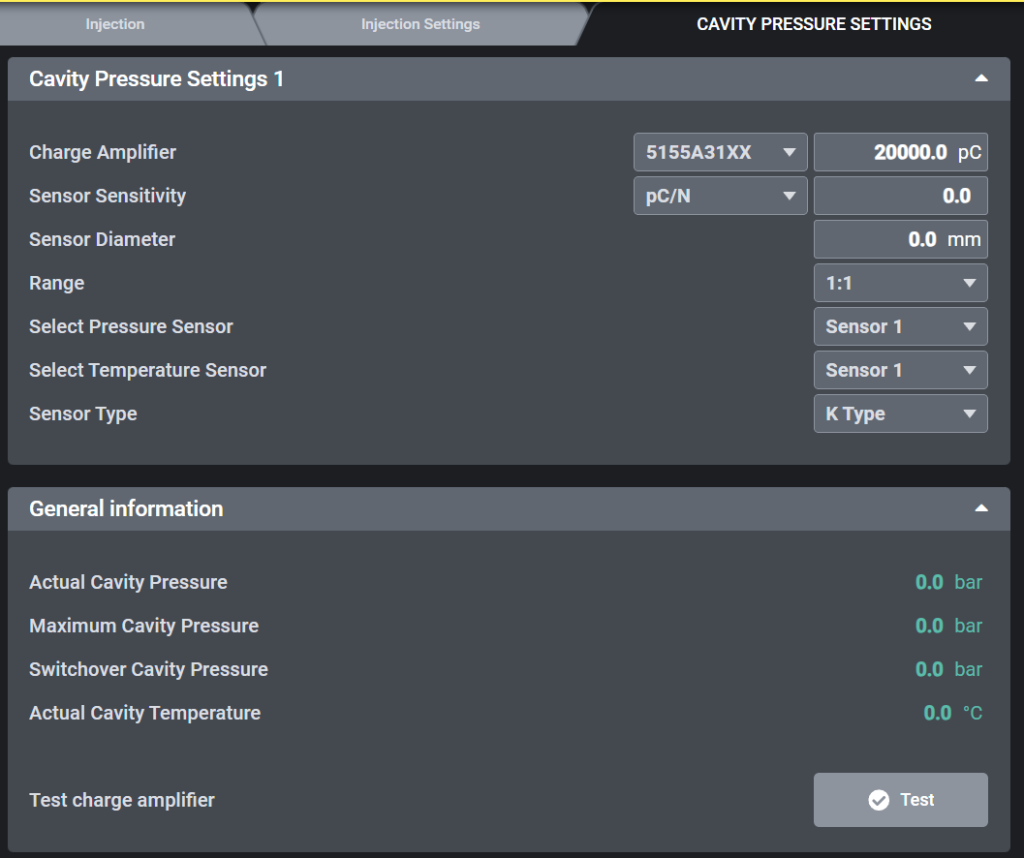
2.1.1 Cavity Pressure Settings 1 #
- Charge Amplifier
- Select the installed amplifier model (e.g., 5155A31XX, 5159A).
- Enter the maximum input charge range (e.g., 20,000 pC).
- Sensor Sensitivity
- Input the sensitivity value from the Kistler sensor datasheet (unit: pC/N or pC/bar).
- This ensures the correct conversion from charge to pressure.
- Sensor Diameter
- Enter the diaphragm size of the installed sensor (e.g., 4.0 mm, 6.0 mm, 8.0 mm).
- Range (Scaling)
- Defines how the measured value is scaled.
- Default: 1:1 (recommended, displays the measured value directly).
- Select Pressure Sensor
- Assign the pressure sensor channel to be used (e.g., Sensor 1).
- Select Temperature Sensor
- Assign the temperature sensor channel (e.g., Sensor 1).
- Sensor Type
- Select the thermocouple type used for temperature measurement.
- Default: K Type, other options (J, L, N) available if required.
2.1.2 General Information #
- Actual Cavity Pressure
- Displays real-time cavity pressure (bar).
- Maximum Cavity Pressure
- Displays the peak cavity pressure reached during the cycle (bar).
- Switchover Cavity Pressure
- Displays the cavity pressure at the point of switchover (bar).
- Actual Cavity Temperature
- Displays the current cavity temperature measured by the sensor (°C).
- Test button
- The Test button is used to check the wiring and functionality of the Kistler amplifier and sensor.
- The button is not available in Auto mode or Semi-auto mode.
- Output signal:
- When the Test button is pressed, the system generates the digital output gDO.CavityTest.
- This signal is sent to the Kistler module, which activates the internal test function of the amplifier.
2.2 Switchover condition settings #
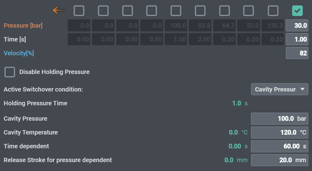
To use cavity pressure and temperature from the Kistler module as the switchover condition during injection:
- Set Active Switchover Condition to Cavity Pressure.
- Enter the Cavity Pressure and Cavity Temperature values to be used for switchover.
- Set the Time dependent parameter as a timeout to prevent process errors.
- Define the injection position where pressure switchover detection begins with Release Stroke for pressure dependent.
3. Kistler Datasheet #
Datasheet link (Type 5159A)
https://kistler.cdn.celum.cloud/SAPCommerce_Download_original/003-468e.pdf
Datasheet link (Type 5155A)
https://kistler.cdn.celum.cloud/SAPCommerce_Download_original/000-403e.pdf


